Top Banner

CTG Series Automatic Transfer Switch ATS MX Contactor


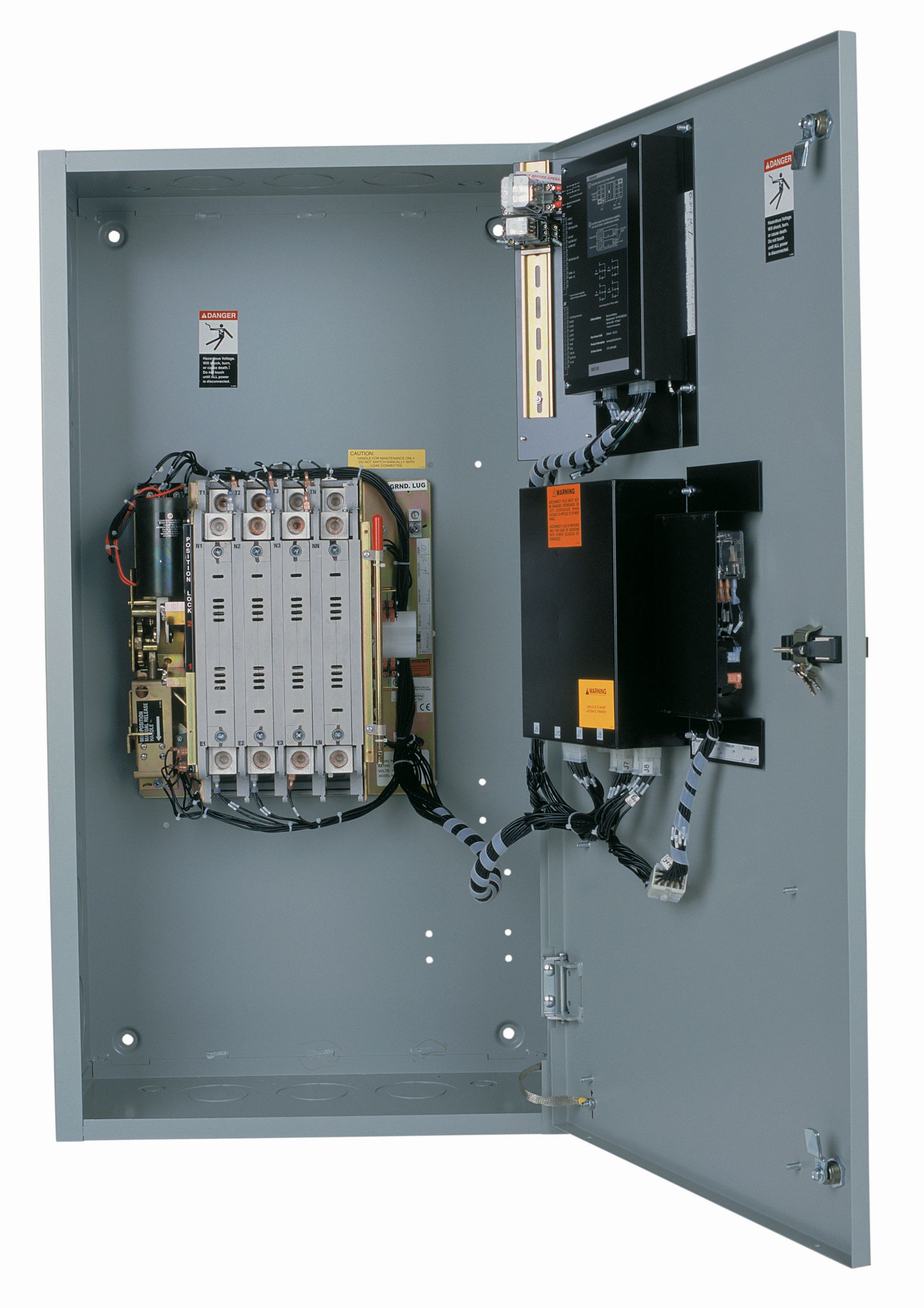
The Catยฎ CTG Series Automatic Transfer Switches (ATS) are pre-configured for applications requiring the dependability and ease of operation found in a full feature power contactor type transfer switch.

CTG switches are equipped with the next generation MX150 microprocessor panel, which controls the operation and displays the status of the transfer switch's position, timers and available sources. As an embedded digital controller, the MX150 offers high reliability and ease of unattended operation across a range of applications.

CTG Series Automatic Transfer Switch

GET A QUOTE

A sales engineer replies within one working day.

The Catยฎ CTG Series Automatic Transfer Switch is built for reliable performance in the electric power range, backed by Al-Bahar's regional service and support network.

Transfer Type
Open transition
Rating Range
40-3000A
Switch Type
Contactor based
Download Brochure
  • Specifications
  • Features
  • Standard Equipment

Specifications

Technical Summary specifications
Transfer Type Open transition
Rating Range 40-3000A
Switch Type Contactor based

Features

Features

  • Ratings 40 to 3000 amps (2, 3 or 4 poles)
  • UL 1008 listed at 480 VAC
  • CSA certified at 600 VAC (200-225 amp - 480V)
  • IEC listed at 480 V
  • Double throw, mechanically interlocked contactor mechanism
  • Electrically operated, mechanically held
  • Designed for emergency and standby applications
  • Available in standard open transition (CTG)or delayed transition (CTGD) models
  • Ringing wave immunity per IEEE 472 (ANSI C37.90A
  • Conducted and Radiated Emissions per EN55022 Class B (CISPR 11) (Exceeds EN55011 & MILSTD 461 Class 3)
  • ESD immunity test per EN61000-4-2 (Level 4)
  • Radiated RF, electromagnetic field immunity test per EN61000-4-3 (ENV50140) 10v/m
  • Electrical fast transient/burst immunity test per EN61000-4-4
  • Radiated RF, electromagnetic field immunity
  • Surge immunity test per EN61000-4-5 IEEE C62.41 (1.2 X 50 ms, 5 & 8 kV)
  • Conducted immunity test per EN61000-4-6 (ENV50141)
  • Voltage dips and interruption immunity EN61000-4-11
  • Seismic Compliance to IEEE-693-2005 and IBC-2003

Design and Construction Features

  • Close differential 3 phase under-voltage sensing of the normal source - factory standard setting 90% pickup, 80% dropout (adjustable);under frequency sensing of the normal source factory setting 95% pickup (adjustable)
  • Voltage and frequency sensing of the emergency source - factory standard setting 90% pickup voltage, 95% pickup frequency (adjustable)
  • Test switch (fast test/load/no load) to simulate normal source failure - automatically bypassed should the emergency source fail
  • Type 1 enclosure is standard - also available in open style or Types 3R, 4, 4X, or 12

Controller

with non-volatile memory-clock battery backup not required for standard switch operation

Automatic Transfer Switches (ATS)

are pre-configured for applications requiring the dependability and ease of operation found in a full feature power contactor type transfer switch

Standard Equipment

Standard Features
  • Auxiliary Contact:
    Closed when the switch is in the normal position
    (Additional contacts optional)
  • Time Delay to Engine Start: Standard setting 3 seconds, adjustable 0-10 seconds
  • Peak Shave/Remote Load Test: Input for peak shave or remote load test; includes automatic return to normal if emergency source fails and normal is present; 120 VAC
  • Indicating LED Pilot Lights:
    -Switch in emergency position
    -Switch in normal position
    - Normal source available
    -Emergency source available
  • When specified for use with a CTGD Series delayed transition switch, the control panel also includes the following:
MX150 Control Panel
  • LED/LCD indicators for ease of viewing and long life
  • Time Delay for Engine Cool Down: Allows engine to run unloaded after switch retransfer to normal; standard setting 5 minutes, adjustable 0-60 minutes
  • Inputs opto-isolated for high electrical immunity to transients and noise
  • Built-in diagnostics with LCD display for immediate troubleshooting
  • Nonvolatile memory (exerciser battery backup not required for standard operation)

Optional Equipment

Options

  • Service entrance configuration
  • Auxiliary Contacts: Closed when the transfer switch is in Source 1 position
  • Elevator Pre-Signal Auxiliary Contacts: Open 0-60 seconds prior to transfer to either direction, re-closes after transfer
  • Space heater and thermostat
  • Auxiliary Contact, operates on Source 1 line failure